
How I went about driving an EL320.240.36 display and why the RP2040 PIO is amazing
November 12, 2023
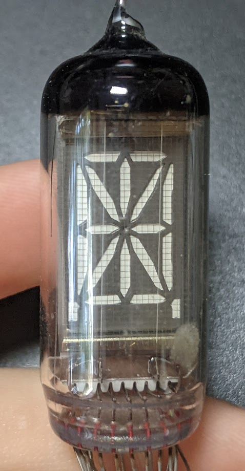
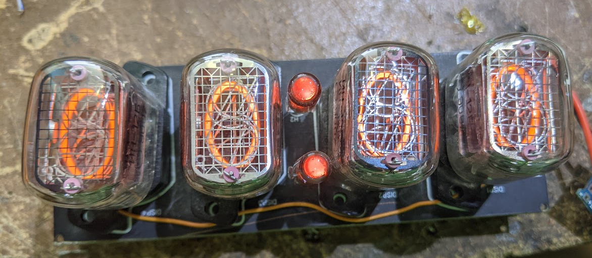
 I have always been fascinated by different display technologies, and try to collect and preserve the unique ones. At the
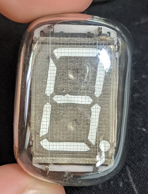
age of 13 I already wanted to build a nixie
clock just because I liked the way they looked. At 15 I ordered a box of POS
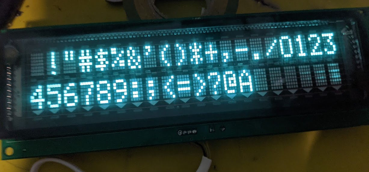
terminals just to extract the VFD displays form them. And when I was 17, I ordered an obscure soviet plasma display just
for the sake of it. These activities have generated a substantial pile of displays that I am yet to do something with,
but at least I am
glad to own them.
I have always been fascinated by different display technologies, and try to collect and preserve the unique ones. At the
age of 13 I already wanted to build a nixie
clock just because I liked the way they looked. At 15 I ordered a box of POS
terminals just to extract the VFD displays form them. And when I was 17, I ordered an obscure soviet plasma display just
for the sake of it. These activities have generated a substantial pile of displays that I am yet to do something with,
but at least I am
glad to own them.

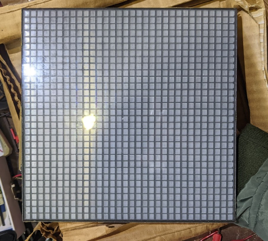
With that in mind, it should come as no surprise that when I saw a weird unlabeled display panel for sale for ~10$
on an
online marketplace, I instantly clicked buy. What I got was something I never even heard of.
 It was an EL320.240.36 electroluminescent display, meaning that unlike other emissive displays that use organic LEDs
or
plasma discharges, this one uses the principle of electroluminescence.
It was an EL320.240.36 electroluminescent display, meaning that unlike other emissive displays that use organic LEDs
or
plasma discharges, this one uses the principle of electroluminescence.
Essentially this display is an array of capacitors with an electroluminescent material between the plates, and whenever the voltage on the capacitor is changing, the electroluminescent layer will create a pulse of light. Applied Science has a few videos going more in depth on the whole EL thing, they can be found here:

As you can imagine pulling something like this off is not easy, and sure enough the back side of the display is a dense circuit board with an FPGA just to get all of the high voltage drive waveforms and whatnot just right so that we get something resembling a display.

Finding documentation wasn't that hard at the time, because the manufacturer had it up on their website, but now they seem to have removed it and forgotten about these older displays. There is a copy of the file on the internet archive for anyone interested in it. Af a matter of fact, the archive seems to heave backed up the entire lineup of these displays.
The documentation describes some interesting quirks that would be unusual for anyone who used a modern LCD type
display:
1. The display has no frame buffer.
2. The display is monochrome.
3. However you can perform PWM dimming in order to obtain in between brightness values.
4. The display suffers from burn in.
5. If you stop pumping data into the display it will just go blank.
6. The display uses a 4 bit parallel interface and two clocks, horizontal and vertical (kind
of
like VGA).
For many of you after seeing that, your hands might start to get itchy to go for the FPGA box and start whipping up your own driver in your favorite HDL. But I object. After having worked on software for a multislope adc using the RP2040 and it's PIO subsystem, I got the idea to try to use that to dive the display after having it bitbanged with an STM32 just to see if I understood the protocol.
I whipped up these pieces of PIO assembly in an evening:
.program driver

; First we configure the X size (X display size / 4 (since we send 4 pixels at a time)),
; after that you dump data in the fifo and the PIO will read it and put it on the data pins 4 bits at a time
; pulsing the VCLK and HS, clock program does the rest of the clocks by reading the interrupts
    pull
    out X, 32           ; X size decrement
    mov Y, X            ; X size constant
    jmp startTransfer   ; jump to start of transfer
lineEnd:
    mov X, Y   [2]      ; copy the value back in to X
    set pins 2 [8]      ; if x is zero that means we reached the end of the row, run a HS pulse and reset the registers
    set pins 0 [5]      ; set the clock pins to 0
.wrap_target
startTransfer:
    jmp x-- transfer    ; if x is not zero go forth and transfer the data
    irq 0               ; fire an interrupt to the other PIO to let it know that we completed a line
    jmp lineEnd         ; go back to the reset code
transfer:
    out pins, 4         ; output the data to the data pins
    set pins 1 [5]      ; set the VLCK pin to 1
    set pins 0 [3]      ; set the VLCK pin to 0
.wrap


.program clock
; send the display Y pixel number as first FIFO transfer.
; Generates VS clock signal for the driver.
    pull
    mov Y, OSR          ; Y size decrement
    mov X, Y            ; Y size constant
    jmp continue        ; jump to start of transfer
frameEnd:
    mov Y, X [20]       ; Y size decrement reset
    set pins 0          ; set the VS pins to 0
.wrap_target
    jmp Y-- continue
    set pins 1          ; set the VS pins to 1
    jmp frameEnd        ; go back to the reset code
continue:
    wait 1 irq 0        ; wait for an interrupt to happen and clear it
.wrap
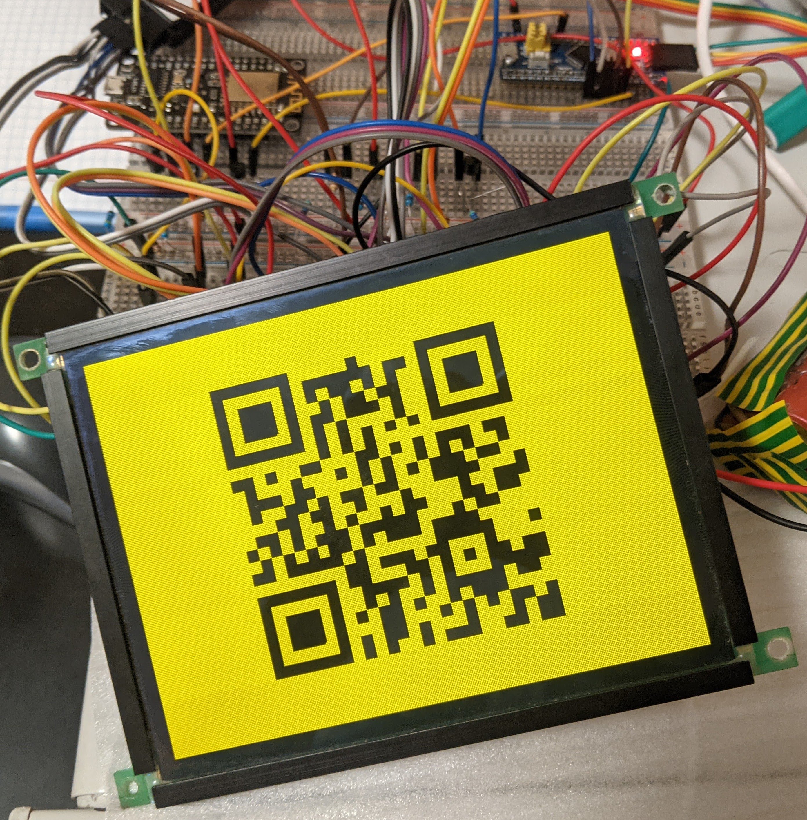
And sure enough the display turned on, it turned on too fast actually. I was pushing ~400Hz though it when it's only rated up to 120Hz. And with that I was able to program some images into the memory of the raspberry pi pico and have them show up on the display, great! But if I want this to be a full on driver I would like to also capture the PWM per pixel dimming, as well as have an interface to send image data to it in real time.

This is when I did the math and realized that with the relatively large amount of RAM I have on the chip, I can store several frame buffers on it. And using DMA I can output them, while filling/processing the inactive one. So that's exactly what I did.

Here PIO handles the exact clocking out of the data to the display, we just feed it the raw binary data we want the display to show.
There are 4 frame buffers:
2x – 320x240x8bits (big buffer) – for storing the requested brightness value from the
host.
2x – 320x240x1bit (small buffers) – for storing the current binary value to be clocked out
into
the display.
And we have 1 variable that controls how the binary buffers are formed:
Current frame counter –
increments after each complete DMA transfer (1 frame) and resets at a value selected by the
user.
The system was intended to work as follows:
After the binary frame buffer is transferred, the DMA fires an interrupt, the interrupt increments the frame counter
variable, changes the "current frame buffer" for the DMA, and asks it to do a transfer on the other buffer. This is
needed because, while DMA is busy putting data into PIO, the 2nd core on the pi pico constantly compares the current
frame counter to the brightness value in the big frame buffer. And if the value on the buffer is above the current
frame, it is turned on and stored in the smaller frame buffer that is currently not being outputted by DMA. In this
way the processing and output of the data is happening in parallel, but if only 1 buffer was used it could cause
tearing, which is why I opted for two separate binary buffers. And since the task of computing things was offloaded
to the
second core, I could just use core 0 to receive data via USB and put it into the big frame buffer.
After I implemented this theoretical approach it almost worked. The problem was that the computation of the binary buffer was too slow for the 8ms frame time required for a 120Hz refresh rate. The first thing I did is set the compiler to do maximum speed optimization, next I removed division and did bitshifting to speed up the calculations. But this still wasn't fast enough. So, this is where I looked into just how fast you can run the RP2040. Turns out that the speed is limited by the QSPI flash, that is only rated for 133Mhz, which you can actually push quite a bit beyond that (to about 200Mhz). Next one can increase the core voltage and add a clock divider to the XIP hardware... And with that you can run pretty much every RP2040 at 400Mhz in a stable manner. I haven't seen it crash or behave weirdly in my entire testing. With this overclock the second core was easily able to keep up with crunching the numbers.
After this came the implementation of a desktop app to stream something interesting to it. I decided that streaming a portion of my display would be the most universal, so that's what I did.
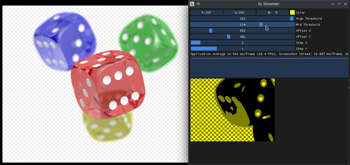
Here I would like to shoutout imgui, it's a wonderful GUI library, a real breath of fresh air after stuff like QT, I hacked together this entire app in an evening and it performs pretty well for being completely unoptimized.
I have a youtube video going more in depth on the exact software implementation:
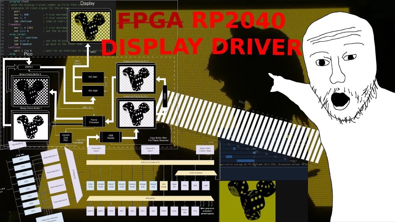
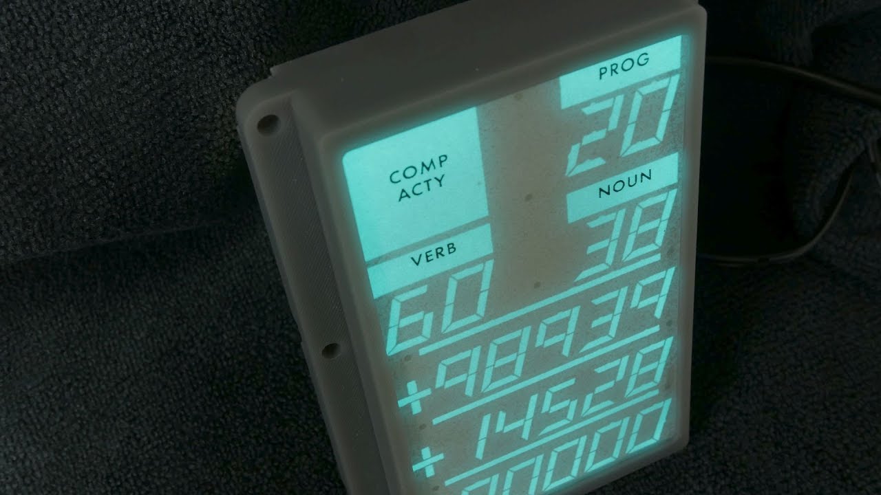
And with that here are some demos of what the display looks like:

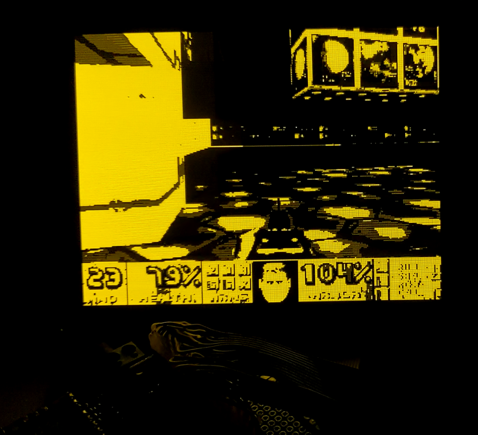
Some curious properties of this display are that you can see some afterglow after a lit pixel goes dark.
Also, you can see something resembling biasing, where the display emits a bit of light even when it is supposed to be blank.
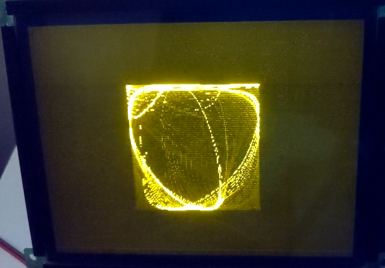
And the last observation is the curious interlaced update cycle that it seems to use.

I think this is done to avoid lighting up an entire row/column when trying to light a pixel by somehow spacing the updates out, but I am not entirely sure about that.
If after reading this you would like to buy such a display, they are available on ebay, but they aren't cheap, I was honestly very lucky that I managed to snag two of them for such a price. Albeit one of them had burn in.